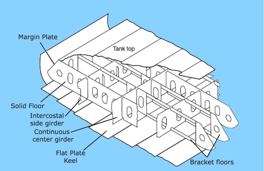

A ship structure is complex webwork of various items and entities made up of different steel breeds, all of which have their importance. Let us look into some essential terms associated with ship construction or crucial aspects of the vessel’s structure.
Before discussing the various tenets of the ship’s structure, it is essential to know about scantlings. The term refers to the dimensions and sizes of the various structural members. Scantling is a direct determinant of the strength of the particular member and resilience against loads.
Calculating it is a crucial part of basic design and precedes any detailed plan. The importance of scantling calculations derives from section modulus, an indicator of the member’s resistance to loads based on the size, form, type, and make of any structural member.
The higher the section modulus of the member, the higher the strength and hence, the ability to withstand higher degree loads.

For all practical purposes, scantling calculations are of two types: Local and Global Scantling Calculations. Global scantling calculation alludes to the determination of hull strength structure as a whole, considering all larger members. Determination of the scantlings and resultant section modulus using the midship section of a vessel is a very commonly used method of determining global scantlings.
On the other hand, local scantling alludes to determining the strength or load-resisting capabilities of individual sections under consideration. Suppose we have a structural panel comprising plating and a network of transverse and longitudinal members. The overall load resisting ability of the panel can be estimated by local scantling calculations from the individual thicknesses of the members, material properties, dimensions, orientation, and overall arrangement.
This is perhaps the most critical structural member of any vessel compared to the backbone or the foundation of any building. Keel is the bottommost structural member of the ship and runs longitudinally unstinted from forward to aft.
All load paths from the structural members in the hull are directed towards the keel, which absorbs a considerable load. Besides these, the keel must also withstand many external loads from the environment when the vessel is underway. Usually, laying the keel is the first step in the construction process of most ships.
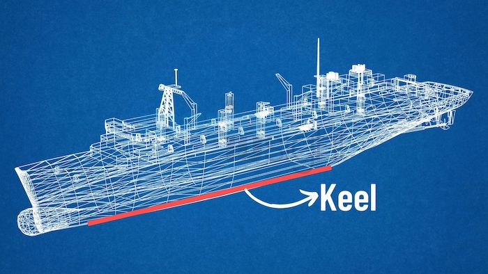
The keel should be aligned with the vessel’s centreline. It has the highest degree of scantlings or dimensions for apparent reasons.
Keels are primarily of three types: i) Flat Plate, ii) Bar Keel, iii) Duct Keel. A flat plate keel is the most common among the three.
The hull structure comprises joined plates whose thickness depends on vessel type and size. As expected, larger ships have heavier scantlings of plates, and smaller vessels have lower values. The plating thickness also depends on the location.
The plating thickness at the bottom and sides is higher than the deck plating. Generally, for all practical purposes, the thickness of the steel plates for smaller vessels (100 mm), it is greater than 10mm.
Now, the plates available for shipbuilding are of various forms. They may be flat or bend depending on the requirement. For example, plates used at deck and side shells are primarily straight, whereas those at the corner locations like bilge areas are bent.
In a broad sense, the plates used are classified as bottom shells, side shells, and deck platings. The types of steel depend on the structural areas and the thicknesses. The most common types of plates used are steel grades A, B, D, or E, including sub-categories.
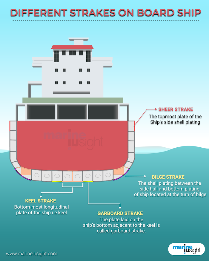
Strakes are plates in the side and bottom structure. The A strake or the Garboard strake are the plates on either side immediately adjacent to the keel. The immediate plates on either side are referred to as strakes B, C, D, and so on. The strake plates at the bottom corners or the turn of the bilge are known as the bilge strakes. Similarly, the outer uppermost side vertical plating at the deck edge is known as sheer strakes.
Vessels have either single or double hulls, like most tankers. The double hull has an external plating system followed by an internal plating system parallel to the outer shell. This is primarily to enhance the strength of the hull and offer protection for structural damages. The spaces between the two hulls on the sides may store ballast, fuel, or bilge water. The inner and outer shells of plating are joined by interspersing structural members.
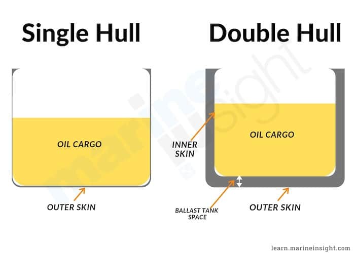
Like single and double hull, a vessel can be a single bottom, for smaller ships, or double bottom, for larger vessels. For double bottoms, an inner shell plating is present at a certain height above the lowermost bottom shell for bolstering strength and protection against flooding. Now, all double hull structures are double-bottom as well, as obvious. However, all double-bottom vessels are not double-hull and may be single-hull at all other places!
Bulkheads are vertical partitions or walls arranged either longitudinally or transversely. The arrangement of bulkheads in longitudinal and transverse directions divides the hull into separate compartments, holds, tanks, or spaces.
The bulkheads may be watertight or oil-tight or may have openings. The main watertight bulkheads are crucial for creating watertight compartments or spaces helpful in maintaining water tightness while dealing with the stability issues of the vessel during flooding. Classification rules decide the number and disposition of the bulkheads based on the size and type of vessel.
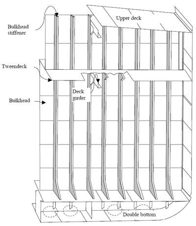
The bulkheads also act as strength members for absorbing loads and preventing structural effects, especially transverse ones. The bulkheads are fabricated based on requirements and are often strengthened by vertical and horizontal support members.
Pillars and stanchions are vertical support members that act as joiners between two successive decks to transfer loads from the upper to the lower deck and subsequently to the bottom structures.
All plates in the hull structure need to be strengthened in various ways to increase their load-absorbing capabilities. For the same reason, stiffening members of multiple types are placed in all directions (transverse and longitudinal). These strength members are standard rolled steel sections or simply plates and bars, depending on the requirement.
Longitudinals are stiffeners that run in a longitudinal direction, i.e., from forward to aft. They resist the longitudinal loads and their effects like bending stresses and buckling and support other connected members. They have definite scantlings and are uniformly spaced depending on the vessel’s bottom and the decks.
The longitudinals placed at the vessel’s side shell platings are called stringers. For double hull configurations, stringers are both for the inner and outer shell.
Girders are heavy scantling longitudinal stiffeners situated at the bottom, sides, and deck, with greater dimensions than longitudinal. Large bars, I-beams, or high scantling L-sections are placed at definite intervals between longitudinals in the top and bottom structure. The keel is often a girder of high dimensions.
The transverse structural members run from the keel to the deck edge at the main deck level. They are usually perpendicular to the outer shell plating and transversely stiffen the outer side shell and outer bottom plating.
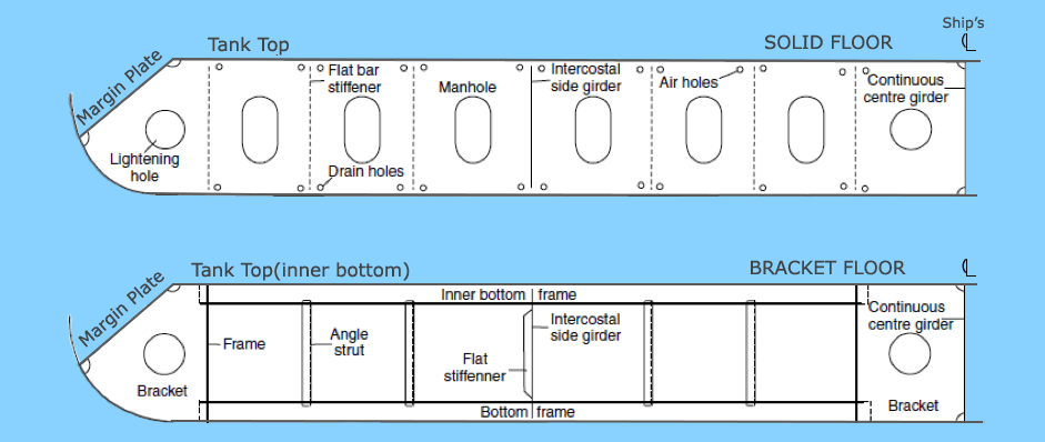
They are a part of the frames in the bottom structure, ideally from the keel to the bilge strake level. Floors have higher scantlings than the part of the frame on the side shells. They usually stiffen the bottom shell plating against lateral loads and, for double bottom constructions, also help support the inner bottom plating. Floors are generally of two types, solid floors and bracket floors.
They are transverse stiffening members running laterally and strengthening the deck plating.
They are supporting members usually between a vertical and horizontal structural member that not only absorbs forces but also creates a continuous load path between members.
For shorter vessels, there are more transverse members like frames than longitudinals, which are comparatively closely spaced. This is due to the effects of lateral loading, and this system is known as transverse framing. Longer vessels are more susceptible to flexural or longitudinal loading effects, and hence they have closely spaced longitudinal members greater than transverse, and this system is known as longitudinal framing.
Hatches are nothing but covers on openings at various deck levels for the access of men, cargo, or other items. These are also stiffened and of a specific strength to compensate for the loss of strength on deck structures due to the openings or cut-outs. They may be watertight or non-watertight.
Bulwarks are high projections from the side shell plating or walls above the main deck level for additional protection. They may be of low scantling but do not contribute much to the vessel strength.
You might also like to read
Disclaimer :
The information contained in this website is for general information purposes only. While we endeavour to keep the information up to date and correct, we make no representations or warranties of any kind, express or implied, about the completeness, accuracy, reliability, suitability or availability with respect to the website or the information, products, services, or related graphics contained on the website for any purpose. Any reliance you place on such information is therefore strictly at your own risk.
In no event will we be liable for any loss or damage including without limitation, indirect or consequential loss or damage, or any loss or damage whatsoever arising from loss of data or profits arising out of, or in connection with, the use of this website.