There are numerous differences between NPN and PNP transistors, and even though both are bipolar junction transistors, the direction of current flow is the name of the game.
Related To: Electronic DesignUpdated 10/26/2022
The transistor is probably the most important invention in electronic engineering and the basis for nearly all integrated circuits (ICs). The transistor is a three-terminal electronic device that can be used to control the flow of electric current, and was the first electronic device that could amplify or switch an electric current. This simple device can be used to create complex electronic circuits, and although there are other types of transistors, bipolar junction transistors are still widely used in digital circuits.
Both are used in various amplification and modulating circuits; the most frequent among its applications is being fully ON and OFF, which is referred to as switch mode. It’s easy to remember that NPN stands for Negative-Positive-Negative and PNP stands for Positive-Negative-Positive. Let’s take a closer look at how NPN and PNP transistors work.
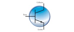
There are two main types of transistor: bipolar junction transistors (BJTs) and field effect transistors (FETs). BJTs are made of doped materials and can be configured as NPN and PNP. A transistor is an active device with three terminals, and these three terminals are known as the Emitter (E), the Base (B), and the Collector (C) (Fig. 1). The Base is responsible for controlling the transistor while the Collector is the positive lead, and Emitter is the negative lead.
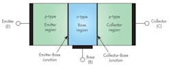
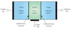
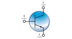
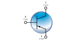
The semiconductor physics of BJTs will not be discussed here, but it is worth mentioning that a BJT is fabricated with three separately doped regions with two junctions. The PNP transistor has one N region between two P regions (Fig. 2) while the NPN transistor has one P region between two N regions (Fig. 3).
The junctions between N and P regions are similar to the junctions in diodes and they can be forward-biased or reverse-biased as well. BJTs can operate in different modes depending on the junction bias:
In an NPN transistor, a positive voltage is given to the collector terminal to produce a current flow from the collector to the emitter. In a PNP transistor, a positive voltage is given to the emitter terminal to produce current flow from the emitter to collector. In an NPN transistor, the current flows from the collector (C) to the Emitter (E) (Fig. 4).
In a PNP transistor, however, the current flows from the emitter to the collector (Fig. 5).
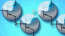
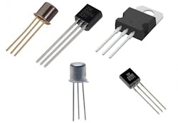
Here is a list of some classic general-purpose BJTs (Fig. 6):
The basic principle of any BJT is to control the current of a third terminal with the voltage between the other two terminals. The principle of operation of NPNs and PNPs is exactly the same. The only difference is in their biasing and the polarity of the power supply for each type.
The future of PNP and NPN transistors is uncertain. They're both well-established technologies with a long history of use. However, newer technologies such as MOSFETs (metal-oxide-semiconductor field-effect transistors) and JFETs (junction field-effect transistors) are becoming increasingly popular, and it's possible that they may eventually replace PNP and NPN transistors.
That said, both transistors are likely to be utilized in next-gen high-speed, low-power devices. PNP transistors have the advantage of a lower turn-on voltage, which makes them ideal for use in high-speed applications. NPN transistors have the advantage of a higher current-carrying capacity, which makes them ideal for use in low-power applications.
Originally published April 13, 2017